Step-by-step guide for assembling and operating the GRLLR Prime G4S Gas Barbecue. It includes detailed instructions for each stage of the process, from initial assembly to safe operation and maintenance.
Product Information
Prime G4S
Elevate your outdoor grilling with the GRLLR Prime G4S Gas BBQ. Crafted for grill masters, it features powerful burners, convenient features, and GrillFlow system for flawless results every time.
Insulated hood for optimal heat preservation
High-power stainless steel split tube burners
Stainless steel flame tamers/flavour bars
Grill flow system for optimal fat removal and safety. Less flare-ups and healthier food.
Attach 2 lock casters (18) and 2 casters (19) to the corners.
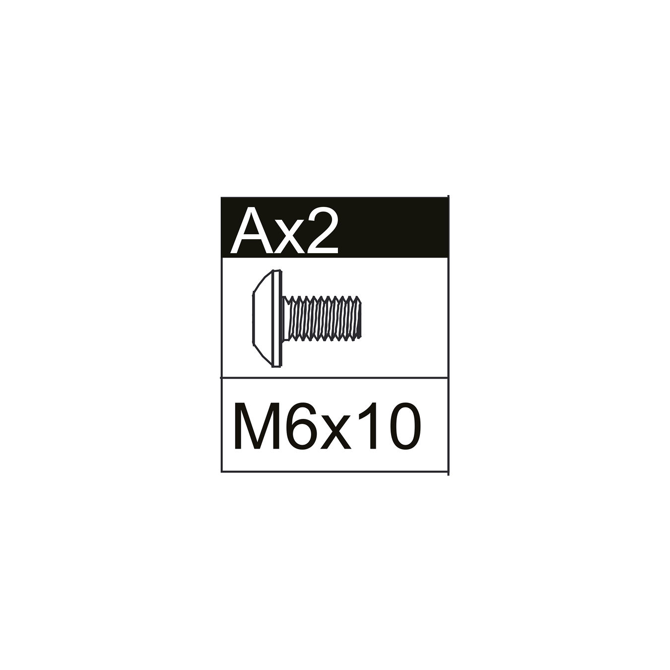
Secure each with M6×10 screws (A).
Fix the plint with M6×12 step screws (B).
 
Parts used:
Bottom Tray | 4BT | 1×
Lock Caster | 18 | 2×
Caster | 19 | 2×
M6×10 Screw | A | 16×
M6×12 Step Screw | B | 2×
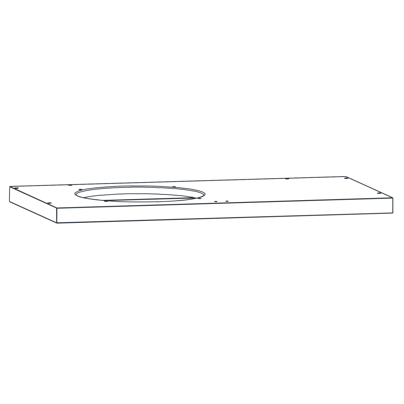
2. Install Door Stopper and Gas Cylinder Brackets
Turn the base upright.
Fix the door stopper (15) at the center back using M4×12 screws (C).
Attach 2 gas cylinder brackets (20) underneath with M6×10 screws (A).
 
Parts used:
Door Stopper | 15 | 1×
Gas Cylinder Bracket | 20 | 2×
M6×10 Screw | A | 4×
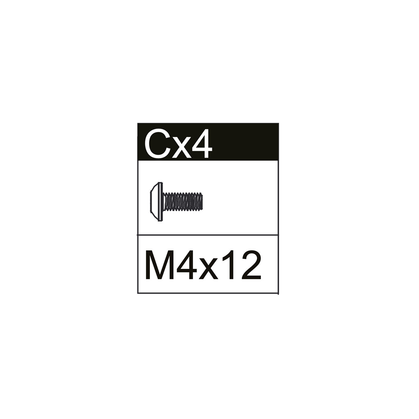
M4×12 Screw | C | 2×
3. Install Hinges on Side Panels
Attach 2 hinges (21) to the left side panel (13) and 2 hinges (21) to the right side panel (14).
Secure each hinge with M4×12 screws (C).
 
Parts used:
Left Side Panel | 13 | 1×
Right Side Panel | 14 | 1×
Hinge | 21 | 4×
M4×12 Screw | C | 16×
4. Attach Side Panels
Fix the left side panel (13) and right side panel (14) onto the bottom tray (4BT).
Secure both panels using M6×10 screws (A).
Parts used:
Left Side Panel | 13 | 1×
Right Side Panel | 14 | 1×
M6×10 Screw | A | 4×
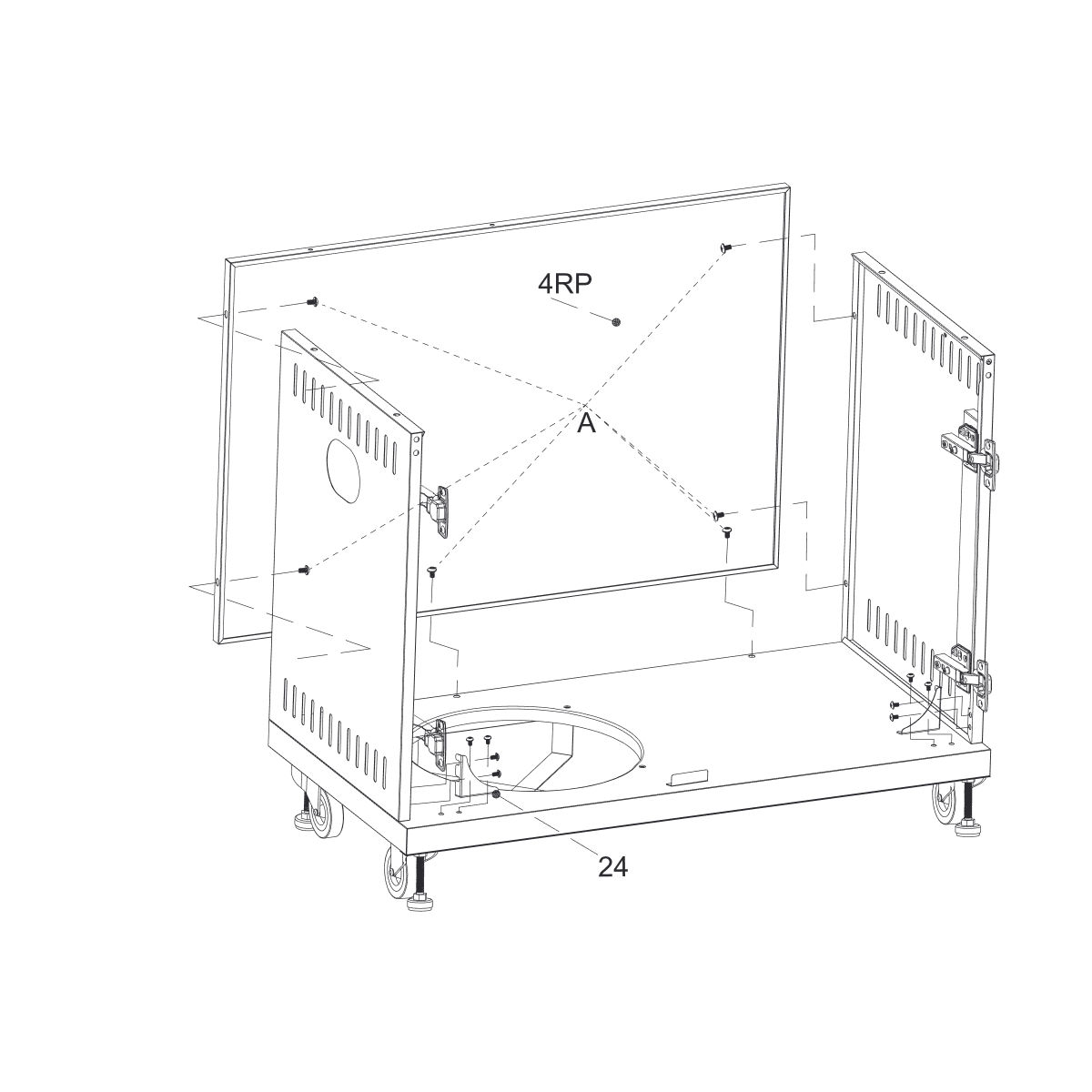
5. Attach Rear Panel and Gas Cylinder Brackets
Position the rear panel (4RP) between the side panels.
Secure it using M6×10 screws (A).
Attach the 2 connect brackets (24) at the bottom, fixing them with M5×10 screws (D).
 
Parts used:
Rear Panel | 4RP | 1×
Connect Bracket | 24 | 2×
M6×10 Screw | A | 6×
M5×10 Screw | D | 8×
6. Attach Door Bracket
Place the door bracket (4DB) across the top of the side panels.
Secure it with M6×10 screws (A).
 
Parts used:
Door Bracket | 4DB | 1×
M6×10 Screw | A | 4×
7. Attach the Bracket
Place the Bracket (25) in the corner
Secure it in place with M6×10 (A) and M5x10 (D) screws.
Parts used:
Bracket | 25 | 1×
M6×10 Screw | A | 6×
M5×10 Screw | D | 2×
8. Install Heat Sheet
Place the heat sheet (10) across the top frame.
Secure it in place with M4×12 screws (C).
 
Parts used:
Heat Sheet | 10 | 1×
M4×12 Screw | C | 4×
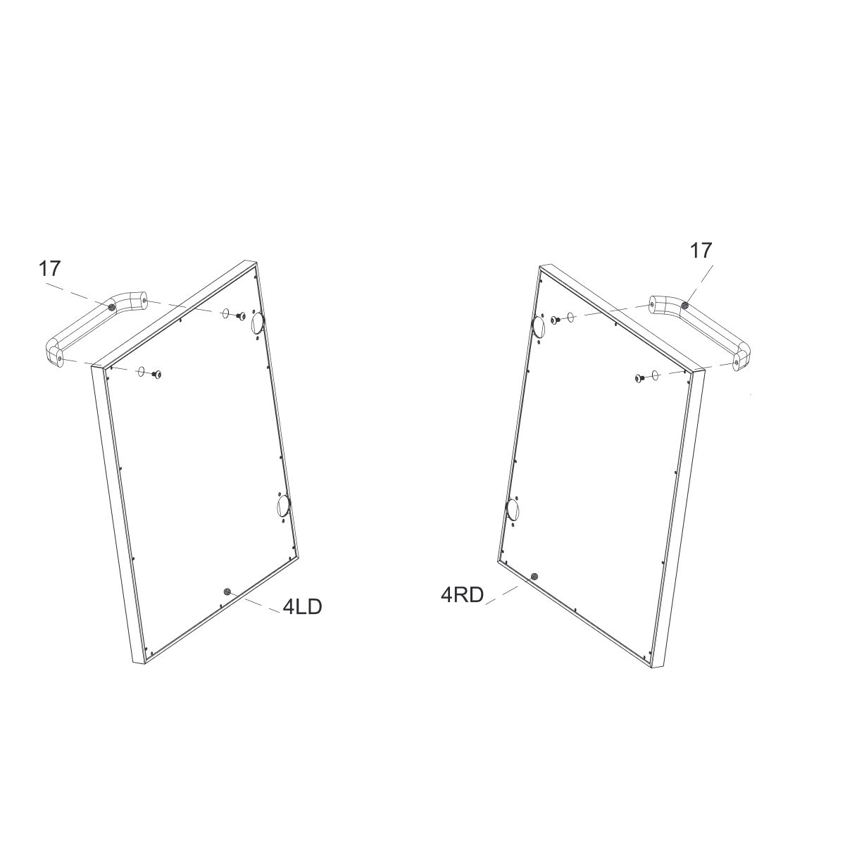
9. Attach Door Handles to Doors
Fix the door handles (17) onto the left door (4LD) and right door (4RD).
Secure each handle with M6×10 screws (A).
 
Parts used:
Left Door | 4LD | 1×
Right Door | 4RD | 1×
Door Handle | 17 | 2×
M6×10 Screw | A | 4×
10. Attach Doors
Hang the left door (4LD) and right door (4RD) onto the hinges (21) fixed to the side panels.
Secure with M4×12 screws (C).
When assembling the unit, you may notice that the doors do not close smoothly. If this happens, it likely means that the walls of the unit are not positioned at a 90o angle, creating a slight imbalance in the structure. Ensure that all screws are properly tightened, the side walls are set at 90o (using a water leveler). 
Parts used:
Left Door | 4LD | 1×
Right Door | 4RD | 1×
Hinge | 21 | already installed
M4×12 Screw | C | 8×
11. Pull Out Knob Cable
Pull the knob cable out from the firebox assembly (4B) through the side opening.
 
Parts used:
Firebox Assembly | 4B | 1×
12. Connect Metal Hose
Connect the metal hose (5) to the main burner valve of the firebox assembly.
Tighten the connection firmly using a wrench.
 
Parts used:
Metal Hose | 5 | 1×
Firebox Assembly | 4B | 1×
13. Install Grease Tray Supports
Fix the grease tray support left (6) and grease tray support right (7) to the underside of the firebox assembly (4B).
Pay close attention to grease tray support orientation.
Secure each support with M6×10 screws (A).
Parts used:
Firebox Assembly | 4B | 1×
Grease Tray Support Left | 6 | 1×
Grease Tray Support Right | 7 | 1×
M6×10 Screw | A | 6×
14. Insert Grease Tray
Fix the grease tray handle (4GH) to the front of the grease tray using M4×12 screws (C).
Slide the grease tray (4GT) into position below the firebox assembly.
 
Parts used:
Grease Tray | 4GT | 1×
Grease Tray Handle | 4GH | 1×
M4×12 Screw | C | 3×
15. Secure Firebox Assembly
Insert screws for firebox assembly (4B)
Insert the M6×10 screws (A) into the bottom of the firebox.
Leave 3-5 mm space for later tightening.
Parts used:
Firebox Assembly | 4B | 1×
M6×10 Screw | A | 4×
16. Secure Firebox Assembly
Position the firebox assembly (4B) onto the cabinet frame.
Fix the assembly securely using M6×10 screws (A).
 
17. Secure Firebox Assembly
Insert the M6×10 screws (A) into the sides of the firebox.
Leave 3-5 mm space for later tightening. 
Note!
When incorporating The Prime Gas BBQ between the Connect Outdoor Kitchen Units, skip forward to step 23. When only one side shelf remains attached, skip the step belonging to the side-shelf that you are leaving out.
Parts used:
Firebox Assembly | 4B | 1×
M6×10 Screw | A | 8×
18. Assemble Side Burner Table
Attach the rear panel of side burner table (3) to the side burner table (2).
Secure with M6×10 screws (A).
 
Parts used:
Side Burner Table | 2 | 1×
Rear Panel of Side Table | 3 | 1×
M6×10 Screw | A | 4×
19. Assemble Side Table (Front Panel)
Attach the front panel of side table (9) to the side table (8).
Secure with M4×12 screws (C).
 
Parts used:
Side Table | 8 | 1×
Front Panel of Side Table | 9 | 1×
M4×12 Screw | C | 4×
20. Assemble Side Table (Rear Panel)
Attach the rear panel of side table (3) to the side table (8).
Secure with M6×10 screws (A).
 
Parts used:
Side Table | 8 | 1×
Rear Panel of Side Table | 3 | 1×
M6×10 Screw | A | 4×
21. Install Side Burner Table
Slide the side shelf into place
Parts used:
Side Burner Table | 2 | 1×
22. Secure Burner Table from Inside
From inside the firebox, fix the side burner table (2) with the additional screw (A).
After securing this screw, return to previous step and fully tighten the four screws installed there.
 
Parts used:
Side Burner Table | 2 | 1×
M6×10 Screw | A | 2×
23. Connect Side Burner Ignition
Connect the ignition wire from the side burner table (2) to the ignition system of the firebox assembly (4B).
Connect the knob tables
Ensure all connections are firmly in place.
 Parts used:
Side Burner Table | 2 | 1×
Firebox Assembly | 4B | 1×
24. Connect Side Burner Hose
Attach the gas hose from the side burner table (2) to the corresponding valve on the firebox assembly (4B).
Tighten the connection securely with a wrench.
Check that the gas hose is firmly connected and not twisted.
Parts used:
Side Burner Table | 2 | 1×
Gas Hose | 5 | 1×
Firebox Assembly | 4B | 1×
25. Connecting the LPG Gas Cylinder to the Appliance
Insert the knob (4) onto the control stems of the firebox assembly (4B).
Ensure each knob is pushed in fully and aligned correctly.
 
Parts used:
Knob | 4 | 1× (per stem)
Firebox Assembly | 4B | 1×
26. Attach Side Table
Position the side table (8) onto the left side of the firebox assembly (4B).
Align the mounting holes
 
Parts used:
Side Table | 8 | 1×
27. Secure Side Table from Inside
From inside the firebox, insert the additional screw (A) to reinforce the side table (8).
After securing this screw, return to the previous step and fully tighten the four screws.
 
Parts used:
Side Table | 8 | 1×
M6×10 Screw | A | 2×
28. Install Grease Cup Bracket
Attach the grease cup bracket (11) beneath the firebox assembly.
Secure it firmly with M6×10 screws (A).
 
Parts used:
Grease Cup Bracket | 11 | 1×
M6×10 Screw | A | 2×
29. Insert Grease Cup
Slide the grease cup (12) into the grease cup bracket (11).
Ensure it is seated securely.
 
Parts used:
Grease Cup | 12 | 1×
Grease Cup Bracket | 11 | already installed
30. Install Battery Compartment Holder
Fix the battery compartment holder (16) onto the inside wall of the cabinet.
Secure with M6×10 screws (A).
 
Parts used:
Battery Compartment Holder | 16 | 1×
M6×10 Screw | A | 2×
31. Install Battery Compartment
Attach the battery compartment (22) into the holder (16).
1. Assemble the extra connector into the gas inlet. 2. Insert the hose into the connector, then tighten the clip.
33. Connecting the gas (no side burner)
Connecting the gas tank when connected with GRLLR Connect Outdoor Kitchen (no side burner):
1. Assemble the extra connector into the gas inlet which is in the cabinet. 2. Insert the hose into the connector then tighten the clip.
34. Connecting the units
Align the rear panel between the left and right side panels.
Secure it using M5×12 screws to attach the connect bracket, ensuring stability and proper alignment with the rest of the structure.
35. Install Cooking Components and Caster Cover
Insert the grease tunnel (4GC) into place.
Place the flame tamers (1) evenly over the burners inside the firebox.
Set the cooking grids (4C) on top of the supports.
Position the warm rack (4R) at the rear inside the hood.
Finally, fix the caster cover (4CC) at the bottom front of the cabinet.
Note!
Plinth should only be attached if the barbecue will remain stationary.
Parts used:
Flame Tamer | 1 | 4×
Cooking Grid | 4C | 2×
Warm Rack | 4R | 1×
Grease Tunnel | 4GC | 1×
Grid Handle | 23 | 1×
Caster Cover | 4CC | 1×
36. Connecting the LPG Gas Cylinder to the Appliance
The appliance may only be used with butane, propane, or a gas mixture LPG for mobile outdoor use. Secure the regulator on the cylinder and use a flexible hose. The hose must be securely connected to the regulator and the appliance with hose clips or screws. Please refer to the technical specification for the appliance’s gas pressure.
37. Gas Cylinder Safety
Always keep the gas cylinder away from any possible ignition in normal use.
For well-ventilated area, handle the gas cylinder.
Always keep the gas cylinder in an upright position.
Do not subject the gas cylinder to excessive heat.
Cylinders should never be stored at temperatures above 50°C.
Never store gas cylinders close to flames, burners or other heat sources.
38. The Type of Gas Cylinder To Be Used
There are many different sizes of gas cylinders available. The maximum diameter and maximum length that should be used:
 
Max Diameter (Bottom): 305mm
Max Height: 580mm
39. Regulator & Hose
The licensee must not supply with the barbecue, but are responsible for supplying the regulator and hose.
When using LPG or butane cylinders (fitted to standard 27mm clip-on regulator) the regulator is factory set at 28-30 mbar.
When using propane cylinders (fitted to standard 37mm regulator) the regulator is factory set at 37 mbar.
For gas cylinders with special connection, it is recommended to request a regulator to 5 years after its first use.
Hoses should be changed when national regulations require.
In case of cracks, damage or change hose to 5 years.
Always keep the hose away from sources of heat or splashes of hot grease.
Keep away from the hot area of the barbecue.
The hose used must conform to local/national requirements.
The length of the hose must not exceed 1.5 meters.
40. Leakage Test — Do This Before Using The Appliance
DO NOT test for gas leakage with an open flame. If you smell gas, turn off the supply immediately.
 
Before each use, you must check for gas leakage as explained in the below procedure:
1. Turn all the appliance knobs to off. 2. Ensure the regulator switch is closed. 3. Connect the regulator to the gas cylinder and open/close valve and gas supply. 4. Spread some soapy water on the hose and apply it with a brush. If any bubbles appear, then there is a leak, which must be repaired before the barbecue is used. 5. Test again once the leak has been repaired. 6. Close the gas inlet valve on the cylinder, after the test is complete. 7. If a leak is detected that cannot be repaired, do not attempt any other action but contact your distributor for assistance.
41. Measures To Perform Before Using The Product For The First Time
When burning off the remaining grease, the appliance produces an unpleasant smoke. This is normal, this smoke will vanish once the grease has burned out.
 
After the leakage test, the grease used during factory storage must be burned off from the grill before it can be used. You can burn off the grease by following the instructions below:
1. Turn and light the three main burners according to the lighting instructions. 2. Set all burners to “MAX” and let it burn for 5 minutes with the hood open. 3. Close the hood and keep the burner at “MAX” for 10 minutes. 4. Close the regulator valve and turn off the burners. 5. Let the appliance cool down for 15 minutes. 6. Clean the cooking grills with a grill-cleaning brush. 7. Grease the cooking grills with cooking oil.
42. Measures To Perform Before Each Usage
Before the gas grill may be used, before each usage, you need to perform a few checks before each use. Carefully go through the checklist below:
 
1. Check that the grill is placed correctly and securely. 2. Check that the grease cup is in place. 3. Check that the gas control knob is created to work. 4. Check that the ignition has fastened tightly. 5. Check that the grill’s bottom, grease tray, flame tamer, and burners are clean and are maintained grease. By doing this, you can prevent grease fires. 6. Check that there are no wires not covered by inserts or vents. 7. Check that there are no bristles from grill brushes stuck to the grill or grids.
43. Lighting Instructions For The Main Burner
1. Open the hood of the grill. 2. Turn the regulator valve on. 3. Push down the control knobs to the “OFF” position. 4. Turn down the control knob and turn it anti-clockwise to the “MAX” position, this will light the burner. 5. When the first burner has been ignited, ignite the remaining burners in order by turning the control knobs to the “MAX” position. 6. Adjust the power of the flame by turning the knob to the MAX/ MIN position. 7. If the burner does not light up, turn the control knob to OFF and wait 5 minutes before attempting to ignite the burner again. If you cannot get the burner to ignite using the piezo ignitor, you can try lighting the burner up with a long match or lighter. 8. To switch off the burner, close the valve on the cylinder or the switch on the regulator if you have finished using the barbecue, then turn the appliance’s control knobs clockwise to the “OFF” position. 9. If the side burner is still in use, just turn the control knobs clockwise to the “OFF” position.
44. Igniting The Burners With A Match (Minimum 90mm Length) Or A Long Lighter
1. Open the hood of the grill. 2. Turn the regulator valve on. 3. Light a long match or lighter. 4. Push down the control knob and turn it anti-clockwise to the “MAX” position. 5. Place a long match or lighter about a centimeter away from the burner. 6. When the first burner has been ignited, you can ignite the remaining burners in order by turning the control knob counter-clockwise.
 
If the burner does not light up within five seconds, turn the control knob to OFF and try to find a solution in the troubleshooting table. Or contact your retailer or distributor.
45. Lighting Instructions For Side Burner
1. Push down the side burner knob and turn it anti-clockwise to the “MAX” position and light the burner. Observe if the burner has lit, if not, repeat this process. 2. Adjust the power of the flame by turning the knob to the MAX/ MIN position. 3. If the burner does not light up, turn the control knob to OFF and wait 5 minutes before attempting to ignite the burner again. If you cannot get the burner to ignite using the piezo ignitor, you can try lighting the burner up with a long match or lighter. 4. To switch off the burner, close the valve on the cylinder or the switch on the regulator if you have finished using the barbecue, then turn the control knobs clockwise to the “OFF” position. If the side burner is still in use, just turn the control knobs clockwise to the “OFF” position.
46. Lighting Instructions For Back Burner (GSS)
1. Push down the back burner knob and turn it anti-clockwise to the “MAX” position and press the pulse ignition button to light the back burner then turn the control knob to the MAX position to light the burner. 2. Adjust the power of the flame by turning the knob to the MAX/ MIN position. 3. If the burner does not light up, turn the control knob OFF and wait 5 minutes before attempting to ignite the burner again. If you cannot get the burner to ignite using the piezo ignitor, you can try lighting the burner up with a long match or lighter.
47. Checking The Flame
Always check the flame when turning the grill on. The burners have been inspected at the factory, but the small holes on the burners nozzles emit a mixed gas when burners are on. When the burners are burning properly, only the tip of the flame is occasionally yellow, and the flame’s color changes from light blue to dark blue.
48. Preheating
Standard Preheating: Allow the BBQ to preheat at full power for 10 minutes which will result in cooking temperatures of 230-260°C (450-500°F)
High-Temperature Preheating (e.g., for Searing): Allow the BBQ to preheat at full for 15 minutes to reach a maximum temperature of 360°C (680°F)
 
Always preheat with the hood closed for faster and more even heating.
49. Creating Heat Zones
The GRLLR Prime makes it easy to create multiple heat zones:
 
Simply adjust the burners individually to achieve higher or lower temperatures across different areas of the grill.
50. Understanding The Hood Temperature Gauge
The temperature gauge located in the hood measures the internal air temperature. This reading is typically lower than the actual temperature at cooking surfaces.
 
For the most accurate temperature monitoring, we recommend using a digital Q Blue tooth thermometer to measure the grill surface directly.
51. Important Usage Note: Grill Plate Safety
When using cast iron grill plates with this BBQ, always ensure at least one cast iron grate remains in place. This precaution is critical to prevent the BBQ from overheating and ensures safe operation.
52. Preventing Rust
Rust is a chemical process in which iron oxidizes and begins to flake as a new metal is created. This will lead to weaker tasks on the metal and come in contact with the metal frequently over time. As an outdoor appliance that is steel, some surface rust should be expected from time to time. Keeping your grill under cover and cleaning often is the best way toward preventing rust from occurring.
 
Some tips are:
1. Ensure cooking surfaces (including flame tamer) are kept clean and dry after cooking, particularly after cooking with marinades. 2. The cooking surface should be rubbed with oil after use. 3. Do not leave the grill out in the rain. 4. Do not store your grill when it is wet. Dry thoroughly first. 5. Ensure the grill is under cover, out of direct sunlight, to be able to maintain your grill, and get rid of any built-up condensation on the surface. 6. Light surface rust can even be removed with a non-toxic cleaner. 7. If a white fungus, or using a commercial rust remover. Dry, rinse affected areas and apply a coating of rust-preventing food oil where appropriate after storage. 8. Barbecues must be treated with touch-up paint to cover the chipped enamel surface.
53. Maintaining Powder-Coated Steel
Frequency: Clean every 3-6 months or more often if the item is exposed to harsh environments (e.g., coastal areas, high pollution).
Method:
Use a soft cloth or sponge with warm water and mild detergent.
Avoid abrasive cleaning tools like steel wool or scouring pads that can scratch the surface.
Use minor clean water to remove any residue.
Dry with a soft cloth to prevent water spots or streaks.
2. Avoid Harsh Chemicals
Do not use solvents, strong alkaline cleaners (e.g., ammonia), or acidic products, as these can damage the powder coating.
Stick to pH-neutral or slightly alkaline cleaning solutions.
3. Protect Against Scratches
Use care when handling or storing powder-coated items to avoid scratching the surface.
If scratches occur, touch them up promptly with a matching paint or protective coating to prevent rust or further damage.
4. Protect from Harsh Conditions
If the powder-coated steel is outdoors:
Use a silicone-based wax, car wax, or a clear protective sealant specifically formulated for powder-coated surfaces.
This adds a water-repellent layer, reducing the chance of water penetration and rust formation.
Reapply every 6–12 months for outdoor items.
5. Inspect Regularly
Check for chips, cracks, or peeling in the powder coating.
Address any damage promptly to prevent rusting or corrosion underneath the coating.
6. Lubricate Moving Parts (if applicable)
For items like hinges or joints, use a silicone-based lubricant to keep them functional and protect against corrosion.
7. Ensure Proper Drainage and Ventilation
Avoid water pooling: Design or place powder-coated items in a way that prevents water from accumulating, such as tilting outdoor furniture slightly for runoff.
Ventilation: Ensure proper airflow around the item to allow quick drying after exposure to rain or cleaning.
8. Apply a Protective Coating:
Products like silicone-based sprays or car wax can repel water and add a shiny finish.
54. Preventing Rust On Stainless Steel
1. Regular Cleaning
Frequency: Clean every 3-6 months or more often if the item is exposed to harsh environments (e.g., coastal areas, high pollution).
Remove Contaminants: Clean stainless steel regularly to remove dirt, salt, grease, or other debris that can lead to rust.
Use warm water and a mild detergent with a soft cloth or sponge.
Rinse thoroughly with clean water and dry with a microfiber cloth to prevent water spots.
Avoid prolonged exposure to saltwater or chloride-based cleaners, as these can corrode stainless steel.
2. Protect the Surface
Apply a Protective Coating: Use a stainless steel polish, wax, or clear protective coating to create a barrier against moisture and contaminants.
Use Passivation Treatments: For higher corrosion resistance, apply a passivating agent (available commercially) to remove iron contaminants and reinforce the chromium oxide layer.
55. Cleaning
Do not wash any parts of the grill in the dishwasher!
56. Cleaning Cooking Grids
Do not use a steel brush intended for welding to clean the grill, as it may damage the grill’s surfaces. The warranty does not cover damage caused by a steel brush.
 
If food or marinade is stuck on the grill or grid, do the following:
1. Check that the grill is turned off. 2. Remove food and grease from the surfaces using, for example, paper towels. 3. Ignite the grill as instructed and set the burners to “MAX”. 4. Close the hood and let the grill heat up for 5–10 minutes. 5. Turn off the grill and open the hood, let the grill cool down for 10 minutes. 6. Brush burned food and dirt off with a cleaning brush intended for grills. 7. Grease the cleaned grilling grids with cooking oil using e.g., paper towels or a cooking brush.
57. Cleaning Grease Tray And Cup
You can make the cleaning easier by using foil on top of the grease tray which allows for easy food and grease removal. When cleaning the tray, you don’t need to remove or throw it off daily. A dirty grease tray is the most common cause of grease fires. If you see deposits of food or marinade on the grease tray or cup, you must clean the grease tray immediately by following the instructions below. The tray must not have grease on it.
 
1. Check that the grill is turned off. 2. Take the grease tray or cup out of the grill. 3. Scrape loose food and grease off with dishwashing liquid, or a grill-cleaning brush, or a plastic spatula. 4. Wash the grease tray or cup with mild dishwashing liquid. 5. Dry the grease tray or cup and place it back on the grill.
58. Cleaning Burners
By grilling burners the most vital part of the grill’s functions and heating. This is why you need to check their cleanliness and condition regularly. You must remove and check the burners at least twice a year, particularly when the grill has been in storage for a long time. The small holes on the burners attract insects and spiders which can build nests. Such obstructions can cause the flame to burn unevenly and improperly. Obstructions may cause the flame to flare up outside the gas pipe, which will damage the grill severely.
 
Clean the burners as follows:
1. Check that the grill is turned off and cooled down. 2. Remove the grilling grids and distributor plates. 3. Remove the burners by gently lifting or loosening the mounting screws which hold the burners to the barbecue. 4. In some grills, removing and cleaning the burners requires that you also remove the back plates of the grill. 5. Shake the burners carefully to ensure that the burners are in good condition. 6. Use a long, thin and non-bend bristle to clean all the burners gas holes. 7. Ensure that the burner holes are open and clean. You can use a thin wire or needle. 8. If the burner is damaged by a badly corroded, replace it immediately. 9. At the same time, check that the valve nozzle is clean and intact. 10. Place the cleaned burners back into the grill.
59. Cleaning Flame Tamers
The flame tamers spread the heat evenly on the grilling surface. The surface of the flame tamers also collects food scraps and marinade. Dirty flame tamers decrease the grill’s efficiency.
 
Clean the flame tamers by following the instructions below:
1. Check that the grill is turned off. 2. Remove the flame tamers from the grill. 3. Scrape food off the tamers’ surface using the scraper part of the cleaning brush or a plastic spatula. 4. Finally, brush off dirt using a brass cleaning brush intended for grills. 5. If you wish, you can also wash the flame tamers in a sink using mild dishwashing liquid. 6. Dry the flame tamers and place them back into the grill.
60. Cleaning Other Grill Components
Caution! Be advised that causes the grill to rust. If the grill is being used in the immediate vicinity of seawater or a pool, the grill must be cleaned after every use.
 
In addition to the components mentioned above, the grill also has many other steel parts that need to be cleaned regularly. You can follow these general instructions below for cleaning such components:
1. Clean the steel parts of the grill with grill cleaning fluid, stainless steel cleaning liquid or mild dishwashing liquid and a cloth. 2. Do not forget to clean and dry the cart carefully. 3. Do not use detergents for cleaning the control panels and the surfaces with warning labels, as they may remove the text or other labels. 4. Clean all the grill’s outer surfaces at least three times a year so that stains do not stick to the surfaces. 5. Always test the suitability of a new detergent in an unnoticeable spot.
61. Storage
Check these instructions if you stop using the grill for a longer time or if you wish to put the grill into storage for the winter, for example. Proper storage prolongs the grill’s service life and keeps it operational for many years. When storing the grill, follow these instructions below:
 
1. Clean the grill completely according to the instructions in the manual. 2. Turn the grill on and let it warm up for 15 minutes so that all the last parts dry off. 3. Let the grill cool down. 4. Ensure that all grill parts are greased. 5. Remove the grilling grids, remove the burners, grids, heating grid and heat distributor plates from the grill. These parts need to be stored in a dry and warm space. It is also recommended that you wrap these parts with greaseproof or something similar so that no surfaces can get oxidated. 6. Remove the UV-pressure regulator from the gas cylinder. 7. Always store the gas cylinder outdoors and ensure that it is not exposed to heat or sunlight. 8. If the grill is stored outdoors, it is recommended that you purchase a high-quality cover for it that will cover it all the way down. Ensure that air can circulate even under the cover.
62. Troubleshooting
Malfunctions may occur in all grills. These malfunctions are usually easily fixable. If you cannot find a solution for your problem in the list below, please contact the retailer or distributor.
63. No Gas Flow
* Regulator valve is off Turn the regulator valve on
- The regulator is not connected to the gas cylinder properly Remove the regulator and connect again - The regulator and hose are faulty Replace the regulator and hose
64. The burner cannot ignite with Integrated push-turn piezo
* The igniter cables are loose or incorrectly installed (for side burner) Check the connections and reinstall the cables
- Faulty assembly of the valve Adjust the ignitor to the burner
65. The burner does not ignite with a match or lighter
The burner’s holes are blocked Clean the burners according to instructions The burners are not properly attached to the valves Check the installation and condition of the burners
66. Not heating up properly
* The air supply into the burners is blocked Check and clean the burners
- Too little gas Replace the full cylinder - Regulator is obstructed Check that the gas hose is intact and not twisted
67. The flame is uneven, completely yellow or smoking
* The burners do not get sufficient air Clean the burners according to instructions
- There is food, salt or marinade stuck on the burner surface Clean the burners according to instructions
68. The flame flares up often or the temperature is too high
* Too much grease and marinade on the food Wipe any extra grease off
- The flame tamer or grease tray are too dirty Clean the flame tamer or the grease tray from excessive food or grease
69. The flame does not stay on
* The wind is too strong Move the grill away from the wind
- Low gas Replace the full cylinder
70. Flames are visible outside the burners
* Obstruction in the burners Check and clean the burners
- Strong wind Move the grill away from wind
71. The pressure regulator is buzzing or humming
* Hot outdoor temperature No actions necessary
- Full gas cylinder A passing situation
72. Warranty
For warranty claims or spare parts, please contact: <customerservice@grllr.com>
To register your GRLLR product, please go to [www.grllr.com](https://grllr.com/)